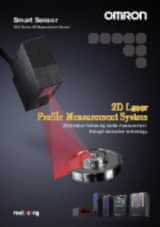
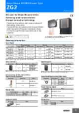
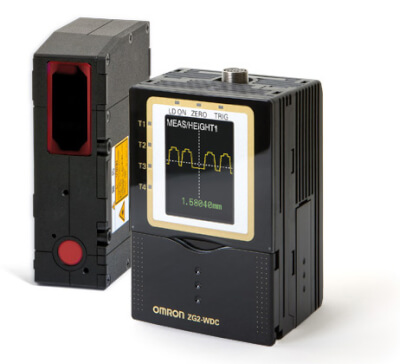
Zaloguj się

Problem techniczny. Akcja nie została wykonana. Przepraszamy - spróbuj ponownie.

Download

Zarejestruj się

Problem techniczny. Akcja nie została wykonana. Przepraszamy - spróbuj ponownie.

Download

Dziękujemy za zainteresowanie

Wiadomość e-mail umożliwiająca dokończenie rejestracji konta została wysłana do

Powrót do strony internetowej

uzyskaj bezpośredni dostęp

Wypełnij poniższe pola i uzyskaj bezpośredni dostęp do zawartości tej strony

Text error notification

Text error notification

Checkbox error notification

Checkbox error notification

Problem techniczny. Akcja nie została wykonana. Przepraszamy - spróbuj ponownie.

Download

Dziękujemy za zainteresowanie

Masz teraz dostęp do ZG2

Wiadomość e-mail z potwierdzeniem została wysłana do

Przejdź do strony

Teraz lub uzyskaj bezpośredni dostęp, aby pobrać ten dokument

ZG2

ZG2

Czujnik pomiaru kształtu

Czujnik ZG2 umożliwia precyzyjny pomiar kształtu na trudnych materiałach i powierzchniach. Łatwy, intuicyjny interfejs umożliwia sprawną instalację, konfigurację i obsługę. Wbudowany wyświetlacz LCD wskazuje wyniki pomiarów w czasie rzeczywistym.

  • Łatwy w użyciu intuicyjny interfejs użytkownika
  • Szybki wbudowany monitor LCD ułatwia konfigurację i pokazuje natychmiast kształt profilu
  • Uniwersalny - 18 funkcji pomiarowych
  • Dokładny - rozdzielczość 5 µm (3 mm / 631 pikseli)
  • Szerokie profile do 70 mm

Modele i specyfikacja

Ordering information

Sensor heads

Optical method

Sensing distance

Resolution

Order code

Height direction

Width direction

Height direction

Width direction

Diffuse reflective

210±48 mm

70 mm

6 µm

111 µm

ZG2-WDS70

Diffuse reflective

100±12 mm

22 mm

2.5 µm

35 µm

ZG2-WDS22

Diffuse reflective

50±3 mm

8 mm

1 µm

13 µm

ZG2-WDS8T

Regular reflective

22.3±0.5 mm

3 mm

0.25 µm

5 µm

ZG2-WDS3VT

Note: - For details, refer the ratings and specifications table.

- Designate the cable length (0.5 m, 2 m) when ordering.

Sensor controllers

Power supply

Output type

Order code

24 VDC

NPN

ZG2-WDC11A1

PNP

ZG2-WDC41A

Accessories (order separately)

Real-time parallel output unit

Output type

Order code

NPN

ZG-RPD11

PNP

ZG-RPD41

RS-232C cable

Connecting device

Order code

For personal computer connection (2 m)

ZS-XRS2

For PLC/PT connection (2 m)

ZS-XPT2

Sensor head extension cable

Name

Order code

3 m extension cable

ZG2-XC3CR

8 m extension cable

ZG2-XC8CR

15 m extension cable

ZG2-XC15CR

25 m extension cable

ZG2-XC25CR

Digital equalizer (relay device)

ZG2-XEQ

0.2 m digital equalizer connection cable

ZG2-XC02D

Parallel mounting adaptor


Order code

For 1 unit

ZS-XPM1

For 2 units or more

ZS-XPM2

Controller link unit

Item

Order code

Controller link unit

ZS-XCN

Memory card

Capacity

Order code

128 MB

F160-N1285

256 MB

F160-N2565

Specifications

Sensor heads

Item

ZG2-WDS70

ZG2-WDS22

ZG2-WDS8T

ZG2-WDS3VT

Optical system

Diffuse reflective

Diffuse
reflective

Regular
reflective

Diffuse
reflective

Regular
reflective

Regular
reflective

Diffuse
reflective

Measurement range

Height direction

210±48 mm
(In the high-precision mode)

100±12 mm

94±10 mm

50±3 mm

44±2 mm

22.3±0.5 mm

10.6±0.4 mm

Width direction (typical)

70 mm

22 mm

8 mm

3 mm

Resolution

Height direction1

6 µm

2.5 µm

1 µm

0.25 µm

Width direction

111 µm
(70 mm/631 pixels)

35 µm
(22 mm/631 pixels)

13 µm
(8 mm/631 pixels)

5 µm
(3 mm/631 pixels)

Linearity (in the height direction)2

±0.1% F.S.

Temperature characteristic3

0.02% F.S./°C

0.03% F.S./°C

0.08% F.S./°C

Light source

Type

Visible semiconductor laser

Wavelength

658 nm

650 nm

Output

5 mW max. output, 1 mW max. exposure (without using optical instruments)

1 mW max.

Laser class

Class 2M of EN60825-1 / IEC60825-1
Class IIIB of FDA (21CFR 1040.10 and 1040.11)

Class 2 of EN60825-1 / IEC60825-1
Class II of FDA (21CFR 1040.10 and 1040.11)

Beam shape (at measurement center distance)4

120 µm × 75 mm (typical)

60 µm × 45 mm (typical)

30 µm × 24 mm (typical)

25 µm × 4 mm (typical)

LED

STANDBY: Lights when laser irradiation preparation is complete (indication color: green)

LD_ON: Lights when the laser is irradiating (indication color: green)

Measurement object

Surface of non-transparent objects

Surface of non-transparent/transparent objects

Environmental

resistance

Ambient light intensity

Illumination on the photo-receiving face 7,000 lx max.: Incandescent lamp

Ambient temperature

Operating: 0 to 50°C, Storage: -15 to 60°C (with no icing or condensation)

Ambient humidity

Operating and storage: 35% to 85% (with no condensation)

Degree of protection

IP66 (IEC60529)

IP67 (IEC60529)

Vibration resistance (destruction)

10 to 150 Hz with 0.35 mm single amplitude for 80 min each in X, Y, and Z directions

Shock resistance (destruction)

150 m/s², 3 times each in 6 directions (up / down, right / left, forward / backward)

Materials

Case: Aluminum diecast, Front cover: Glass, Cable insulation: Heat-resistive polyvinyl chloride (PVC),
Connector: Zinc alloy or brass

Cable length

0.5 m, 2 m (flexible cable)

Weight

Approx. 650 g

Approx. 500 g

Approx. 300 g

Accessories

Laser labels (EN: 2 labels, FDA: 3 labels), Ferrite core (1), Instruction manual

*1 Obtained by setting an Omron standard measurement object at the measurement center distance and determing the average height of the beam line. The conditions are given in the table below. However, satisfactory resolution cannot be attained in strong electromagnetic fields.The minimum resolution of the ZG2-WDS8T/WDS3VT is 0.25 ƒÊm, even when the average number of operations is increased. Resolution does not go any lower.

Model

CCD Mode

Average No. of operations

Measurement object

Regular reflective

Diffuse reflective

ZG2-WDS70/WDS22/WDS8T

Standard mode

64

Omron standard white alumina ceramic object

ZG2-WDS3VT

Standard mode

Omron standard mirrored object

Omron standard diffuse reflective object

*2 The tolerance for an ideal straight line obtained by determing the average height of an Omron standard measurement object for the beam line. The CCD high-resolution mode is used. Linearity varies depending on the measurement object.

Model

Measurement object

Regular reflective

Diffuse reflective

ZG2-WDS70/WDS22/WDS8T

Omron standard white alumina ceramic object

ZG2-WDS3VT

Omron standard mirrored object

Omron standard diffuse reflective object

*3 A value attained by using an aluminum jig to secure the distance between the Sensor head and the measurement object. The CCD standard mode is used.

*4 Defined as 1/e 2 (13.5%) of the center light intensity. This may be influenced when light leakage also exists outside the defined area and the reflectivity of the light around the measurement object is higher than that of the measurement object.

Sensor controllers

Item

ZG2-WDC11/WDC11A

ZG2-WDC41/WDC41A

Input/output type

NPN

PNP

No. of connectable Sensor Heads

1 per Controller

No. of connectable Controllers

2

Measurement cycle 2

16 ms (high-precision mode), 8 ms (standard mode), 5 ms (high-speed mode)

Min. display unit

10 nm

Display range

-999.99999 to 999.99999

Display

LCD monitor

1.8-inch TFT color LCD (557x234 pixels)

LEDs

  • Judgment indicators for each task (indication color: orange): T1, T2, T3, T4
  • Laser indicator (indication color: green): LD_ON
  • Zero reset indicator (indication color: green): ZERO
  • Trigger indicators (indication color: green): TRIG

External
interface

Input/output
signal lines

Analog outputs

Select voltage or current (using the sliding switch on the bottom surface)

  • Voltage output: 10 to 10 V, output impedance: 40 Ω
  • Current output: 4 to 20 mA, maximum load resistance: 300 Ω

Judgment output
(ALL-PASSING/ERROR)

NPN open collector

30 VDC, 50 mA max.

Residual voltage: 1.2 V max.

PNP open collector

50 mA max.

Residual voltage: 1.2 V max.

Trigger auxiliary output
(ENABLE/GATE)

Laser stop input (LD-OFF)

ON: O V short or 1.5 V max.

OFF: Open (leakage current: 0.1 mA max.)

ON: Power supply voltage short or
power supply voltage -1.5 V max.

OFF: Open (leakage current: 0.1 mA max.)

Zero reset input (ZERO)

Measurement trigger input (TRIG)

Bank switching input (BANK A, B)

Serial I/O

USB2.0

1 port, full speed (12 Mbps), MINI-B

RS-232C

1 port, 115,200 bps max.

Parall output3

Output

18 - terminal

Main functions

No. of settings banks

16

Sensitivity adjustment

Multi, High-speed multi, Auto, Fixed

Measurement items

Height, 2-point Step, 3-point Step, Edge position, Edge width, Angle, Intersection coordinates, Intersection angle, Sectional area

(up to eight items can be measured simultaneously)

Auxiliary functions

Filter, Laser power adjustment, Position correction (height, position, lope), Linked operation, Point of inflection measurement

Profiles saved

16 profiles (1 profile per bank)

Trigger modes

External trigger/continuous

Ratings

Power supply voltage

21.6 to 26.4 VDC (including ripple current)

Current consumption

0.8 A max. (per sensor head)

Insulation resistance

20 M Ω at 250 V between lead wires and Controller case

Dielectric strength

1,000 VAC, 50 / 60 Hz for 1 min between lead wires and Controller case

Environmental resistance

Ambient temperature

Operating: 0 to 50°C, Storage: -15 to 60°C (with no icing or condensation)

Ambient humidity

Operating and storage: 35% to 85% (with no condensation)

Degree of protection

IP20 (IEC 60529)

Vibration resistance (destruction)

Vibration frequency: 10 to 150 Hz, single amplitude: 0.35 mm, acceleration: 50 m/s²

Shock resistance (destruction)

150 m/s², 3 times each in 6 directions (up/down, right/left, forward/backward)

Material

Case: Polycarbonate (PC),

Cable insulation: Heat-resistive polyvinyl chloride (PCV)

Cable length

2 m

Weight

Approx. 300 g (including cable) (Packed state: Approx. 450 g)

Accessories

ZG2-WDC_1: Large Ferrite Core (1 piece), Instruction Manual

ZG2-WDC_1A: Large Ferrite Core (1 piece), Small Ferrite Core (2 pieces), Instruction Manual, Setup Support Software (CD-ROM), USB cable (1 m)

Data storage unit

Item

ZG2-DSU11

ZG2-DSU41

Input/output type

NPN

PNP

No. of connectable Controllers

24

Connectable controllers

ZG2-WDC11/WDC41

External
interface

Input/output
signal lines

Inputting starting/

terminating logging

ON: O V short or 1.5 V max.

OFF: Open (leakage current: 0.1 mA max.)

ON: Power supply voltage short or power supply voltage
-1.5 V max.

OFF: Open (leakage current: 0.1 mA max.)

Judgment output

(HIGH/PASS/LOW/ERROR)

NPN open collector
30 VDC, 50 mA max.

Residual voltage: 1.2 V max.

PNP open collector
50 mA max.

Residual voltage: 1.2 V max.

Serial I/O

USB2.0

1 port, full speed (12 Mbps), MINI-B

RS-232C

1 port, 115,200 bps max.

Functions

No. of logged data5

Memory of the main unit

Profiles saved: 5,120 profiles

Measurement values saved: 65,000 values max.6

Memory card (256 MB)7

Profiles saved: 35,328 profiles max. (256 profiles x 138 files)

Measurement values saved: 7,150,000 values max. (65,000 values x 110 files)

Logging trigger functions

External triggers, data triggers (self-triggers), and time triggers

External banks functions

4096

Other functions

Alarm output functions

Ratings

Power supply voltage

21.6 to 26.4 VDC (including ripple current)

Current consumption

0.5 A max.

Environmental resistance

Ambient temperature

Operating: 0 to 50°C, Storage: 0 to 60°C (with no icing or condensation)

Ambient humidity

Operating and storage: 35% to 85% (with no condensation)

Material

Case: Polycarbonate (PC)

Cable length

2 m

Weight

Approx. 280 g

Accessories

Ferrite Core (1 piece), Instruction Manual


1. Setup support software for PC is attached

2. The image input periods listed here are for fixed/auto sensitivity. The image input period will be longer for multi-sensitivity, high-speed multi-sensitivity, or other settings. When the high-power mode is ON, the shortest image input period is 95 ms regardless of the setting of the CCD mode. Use the eco monitor in the RUN mode to determine the actual image input period.

3. when ZG-RPD is mounted

4. The controller link unit is necessary for linking.

5. Data is saved in the memory of the main unit during logging. The data is automatically saved in a memory card after logging is completed. The maximum number of logging differs according to set conditions. For details, refer to the Users Manual.

6. Measurement values for 65,000 measurements can be saved even when two sensor controllers are connected and each performs eight tasks.

7. The value is the maximum number achieved in the following conditions:
• One sensor controller performs one measurement task.
• Either profiles or measurement values are logged.

Jak możemy Ci pomóc?

W razie pytań lub chęci przesłania prośby o wycenę skontaktuj się z nami lub wyślij zlecenie.

+48 22 458 6666
Skontaktuj się z nami

Proszę o kontakt ZG2

zg2 sensorhead prod

Prosimy wypełnić wszystkie pola oznaczone *. Twoje dane osobowe będą oczywiście traktowane jako poufne.

Text error notification

Text error notification

Text error notification

Text error notification

Country error notification

Text area error notification

Checkbox error notification

Checkbox error notification

Dziękujemy za wysłanie zapytania. Otrzymasz od nas odpowiedź tak szybko, jak to tylko będzie możliwe.

Problem techniczny. Akcja nie została wykonana. Przepraszamy - spróbuj ponownie.

Download
+48 22 458 6666
+48 22 458 6666
Zapytaj o ofertę
Zapytaj o ofertę

Oferta dla ZG2

Poniżej możecie Państwo wysłać zapytanie cenowe dotyczące naszych produktów. Prosimy wypełnić wszystkie pola oznaczone *. Twoje dane osobowe będą oczywiście traktowane jako poufne.

zg2 sensorhead prod

Dane osobowe

ZG2

Text error notification

Text error notification

Text error notification

Text error notification

Country error notification

Szczegóły oferty

Select notification error

Select notification error

Text area error notification

Checkbox error notification

Checkbox error notification

Dziękujemy za zlecenie wyceny. Dostarczymy Ci niezbędnych informacji tak szybko, jak to tylko będzie możliwe.

Problem techniczny. Akcja nie została wykonana. Przepraszamy - spróbuj ponownie.

Download
Zapytaj o ofertę
Zapytaj o ofertę

Cechy

Width - Car body

The sensor checks the correct width between different parts of the car body.

Bottom PCB board

The sensor checks the warpage of a PCB board to avoid soldering or connection defects.

Area glue bead

The sensor checks the area (shape) of the glue to control the continuous motion of a robot.

Position – Sheet

The sensor checks the wandering of paper over time in order to detect drifts.

Angle – Seat

The sensor checks the differences of seat angles. The controller allows you to calculate various angles via the definition of additional tasks.

Materiały