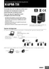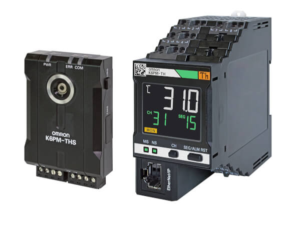
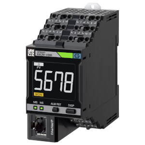
K6PM-TH
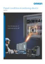
Monitorowanie stanu w oparciu o termografię
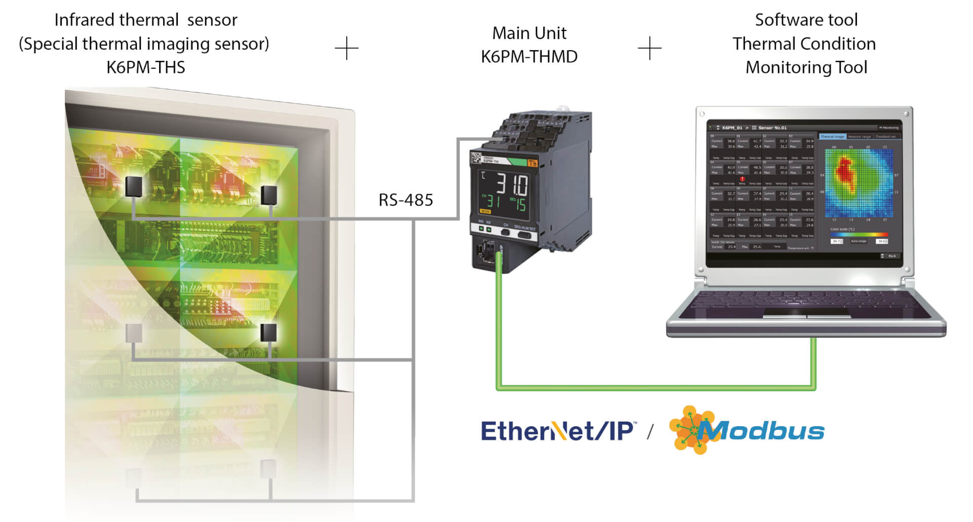
K6PM-TH mierzy i monitoruje temperaturę powierzchni za pomocą maksymalnie 31 dołączonych kamer podczerwieni, jako ciągłą termografię.
- Monitorowanie i przewidywanie trendu temperatury, sygnalizując alarm zawsze, gdy temperatura danego obszaru przekracza ustawiony próg lub oczekuje się, że w niedalekiej przyszłości osiągnie wartość krytyczną
- Uwzględnianie trendu różnicy temperatur (pomiędzy środowiskiem a mierzonym obiektem), sygnalizując alarmy tylko w przypadku wystąpienia krytycznych warunków.
- Automatyczne ustawianie progu temperatury dla każdego obszaru (każda kamera dzieli monitorowany obszar na 16 kwadrantów) w oparciu o warunki odniesienia
- Powiadomienia e-mail w przypadku ostrzeżenia/alarmu
- Zdalne monitorowanie
- Interakcja z aplikacjami niestandardowymi i serwerem MQTT
Modele i specyfikacja
| Produkt | Supply voltage AC | Supply voltage DC | Opis | |
|---|---|---|---|---|
|
|
20.4-26.4 V | 20.4-26.4 V | Thermal condition monitoring device for control cabinets and panels, 24 VDC, transistor control output, Push-in Plus, LCD display, EtherNet/IP and Modbus TCP |
|
Jak możemy Ci pomóc?
W razie pytań lub chęci przesłania prośby o wycenę skontaktuj się z nami lub wyślij zlecenie.
Proszę o kontakt K6PM-TH

Dziękujemy za wysłanie zapytania. Otrzymasz od nas odpowiedź tak szybko, jak to tylko będzie możliwe.
Problem techniczny. Akcja nie została wykonana. Przepraszamy - spróbuj ponownie.
DownloadOferta dla K6PM-TH
Poniżej możecie Państwo wysłać zapytanie cenowe dotyczące naszych produktów. Prosimy wypełnić wszystkie pola oznaczone *. Twoje dane osobowe będą oczywiście traktowane jako poufne.
Dziękujemy za zlecenie wyceny. Dostarczymy Ci niezbędnych informacji tak szybko, jak to tylko będzie możliwe.
Problem techniczny. Akcja nie została wykonana. Przepraszamy - spróbuj ponownie.
DownloadFeature
K6PM jest niezawodnym partnerem do monitorowania krytycznych paneli placówki, a także paneli urządzeń przez cały okres ich eksploatacji (rozwój, walidacja, FAT i po instalacji).
Nadaje się w szczególności do zastosowań, w których panel znajduje się tuż obok maszyny generującej intensywne ciepło (piece, piekarniki, maszyny do formowania).
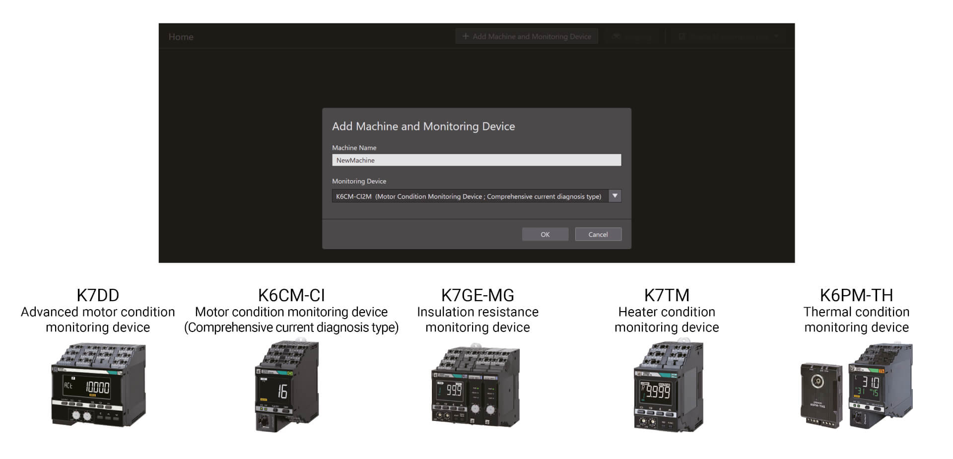
Urządzenia do monitorowania stanu można skonfigurować za pomocą jednego narzędzia
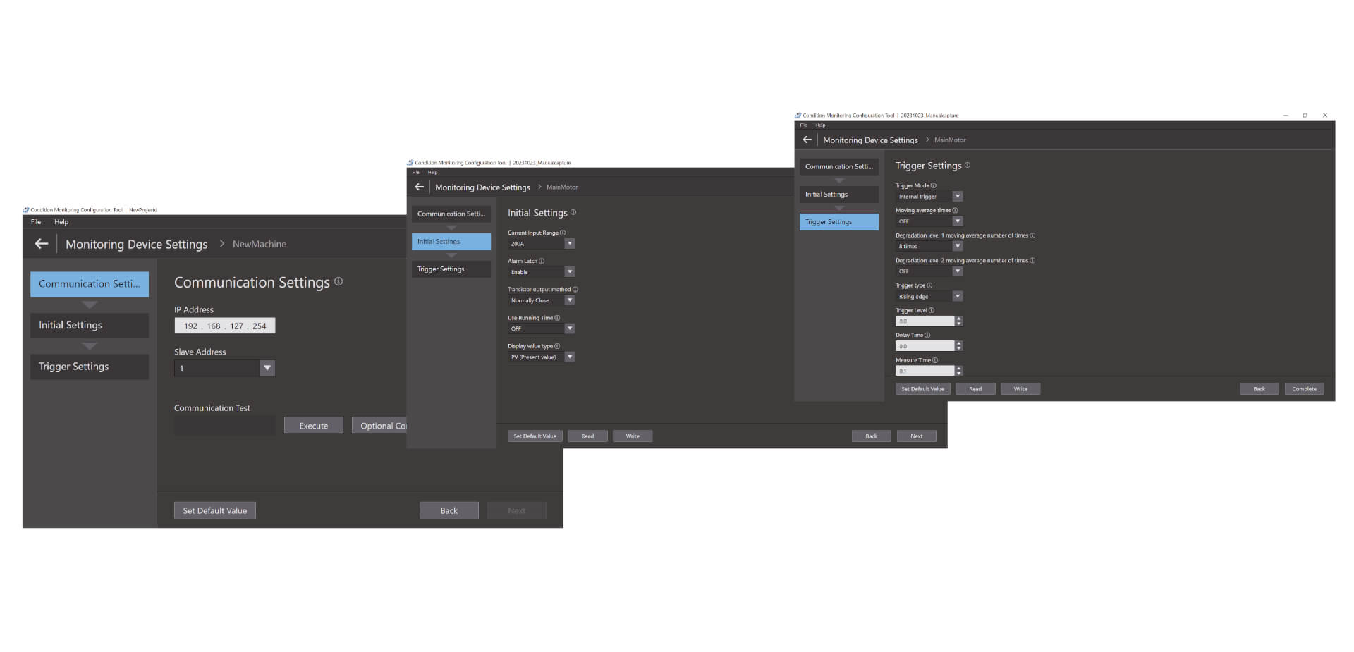
Łatwa konfiguracja w trzech krokach Narzędzie do konfiguracji monitorowania stanu umożliwia konfigurację wsadową szerokiej gamy urządzeń do monitorowania stanu, na przykład silników, temperatury, izolacji i elementów grzejnych. Do jego obsługi nie są wymagane żadne specjalne umiejętności, co zmniejsza wysiłek poświęcony na szkolenie.
Łatwa konfiguracja w trzech krokach
Narzędzie do konfiguracji monitorowania stanu umożliwia konfigurację wsadową szerokiej gamy urządzeń do monitorowania stanu, na przykład silników, temperatury, izolacji i elementów grzejnych. Do jego obsługi nie są wymagane żadne specjalne umiejętności, co zmniejsza wysiłek poświęcony na szkolenie. Konfigurację można ukończyć w zaledwie trzech krokach, są to: konfiguracja komunikacji, wstępna konfiguracja i konfiguracja wyzwalania. *1 Dzięki wysokiemu poziomowi funkcjonalności narzędzie zwiększa również wydajność w zakładzie.
Filmy
-
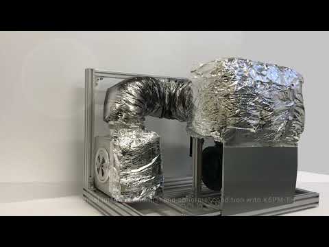
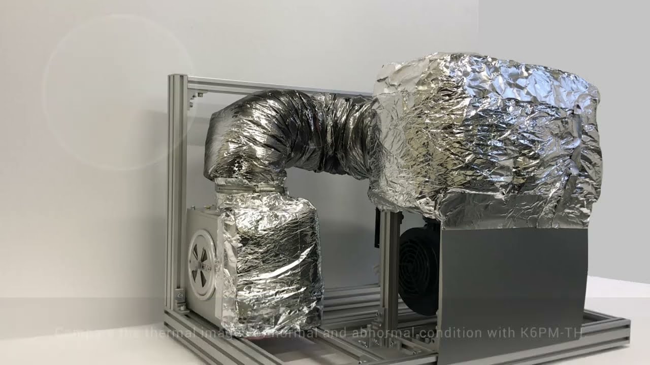
OMRON K6PM-TH Thermal Condition Monitor Detecting Dryer Duct Leak
Coating and drying is one of the most dangerous processes in car manufacturing. In the drying oven, air heated to 400°C in the combustion chamber travels through the air duct for use in drying. These air ducts degrade over time, sometimes allowing air hotter than 100°C to leak, which can lead to burn injuries during patrol inspection. #omronindustrialautomation #MakeitOMRON
02:59
OMRON K6PM-TH Thermal Condition Monitor Detecting Dryer Duct Leak
Coating and drying is one of the most dangerous processes in car manufacturing. In the drying oven, air heated to 400°C in the combustion chamber travels through the air duct for use in drying. These air ducts degrade over time, sometimes allowing air hotter than 100°C to leak, which can lead to burn injuries during patrol inspection. #omronindustrialautomation #MakeitOMRON
-
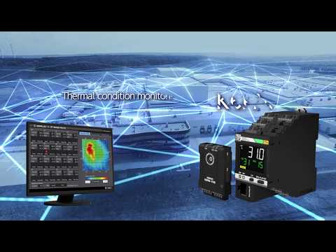
K6PM: Innovation in thermal monitoring and panel maintenance
Parts to check are increasing as devices and wires in a panel increase for high-functioned facilities and equipment. On the other hand, maintenance frequency is decreasing due to shortage of the maintenance engineers, resulting in a higher risk of accident. There are various causes of failures on the device. Current methods of manual inspections are useful but they only provide limited amount of failure detection information. Here is a new solution from OMRON.
02:37
K6PM: Innovation in thermal monitoring and panel maintenance
Parts to check are increasing as devices and wires in a panel increase for high-functioned facilities and equipment. On the other hand, maintenance frequency is decreasing due to shortage of the maintenance engineers, resulting in a higher risk of accident. There are various causes of failures on the device. Current methods of manual inspections are useful but they only provide limited amount of failure detection information. Here is a new solution from OMRON.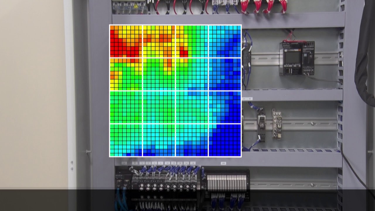
-

Omron K6PM "Auto threshold set" algorithm
The amount of heat generated varies from device to device. For this reason, the optimum threshold value for the thermal monitoring must be set depending on the device. K6PM can divide one sensor monitoring area into 16 segments and automatically set the threshold for each segment.
01:27
Omron K6PM "Auto threshold set" algorithm
The amount of heat generated varies from device to device. For this reason, the optimum threshold value for the thermal monitoring must be set depending on the device. K6PM can divide one sensor monitoring area into 16 segments and automatically set the threshold for each segment.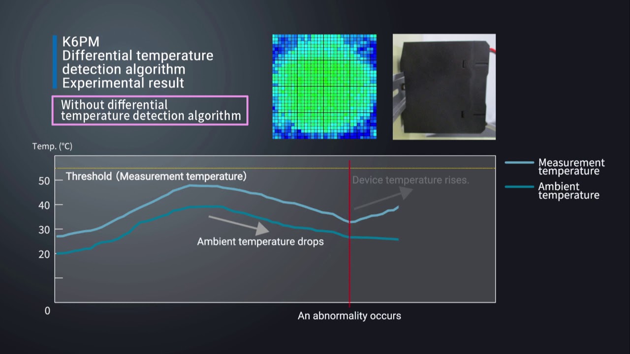
-

Omron K6PM "Differential temperature detection" algorithm
For applications where there are fluctuations in ambient temperature, it can be difficult to determine the cause of the temperature change of the device. The K6PM constantly monitors the difference between measure temperature and ambient temperature. This allows the K6PM to accurately detect abnormalities without being affected by ambient temperatures.
01:51
Omron K6PM "Differential temperature detection" algorithm
For applications where there are fluctuations in ambient temperature, it can be difficult to determine the cause of the temperature change of the device. The K6PM constantly monitors the difference between measure temperature and ambient temperature. This allows the K6PM to accurately detect abnormalities without being affected by ambient temperatures.
-

Omron K6PM "Arrival prediction" algorithm
Predicts the estimated temperature value based on the temperature rise trend. With the Predictive temperature algorythm, you can quickly identify potential risks before they ccould lead failures and machine downtime. Watch a testing example.
01:52
Omron K6PM "Arrival prediction" algorithm
Predicts the estimated temperature value based on the temperature rise trend. With the Predictive temperature algorythm, you can quickly identify potential risks before they ccould lead failures and machine downtime. Watch a testing example.
-

Installation procedure of thermal image sensor (K6PM-THS) in the panel
Watch the installation video for a smooth integration of the K6PM.
02:33
Installation procedure of thermal image sensor (K6PM-THS) in the panel
Watch the installation video for a smooth integration of the K6PM.Rozwiązania
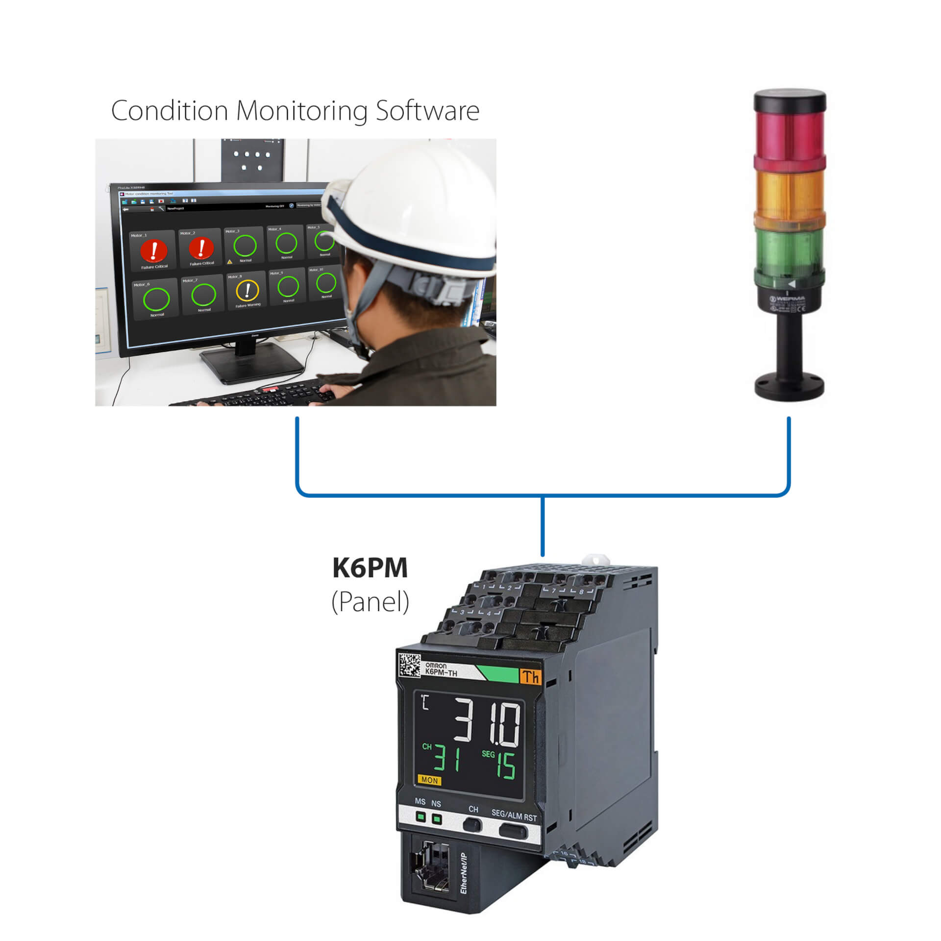
Instalacja autonomiczna (bez sterownika PLC)
To proste rozwiązanie umożliwia:
- Monitorowanie stanu silnika za pomocą wbudowanej diody LED lub poprzez oprogramowanie do monitorowania stanu
- Konfigurowanie sterowników za pomocą oprogramowania do monitorowania stanu dostarczonego z urządzeniem
- Korzystanie z interfejsu urządzenia K6PM z zewnętrznymi urządzeniami we/wy (wyjście cyfrowe)
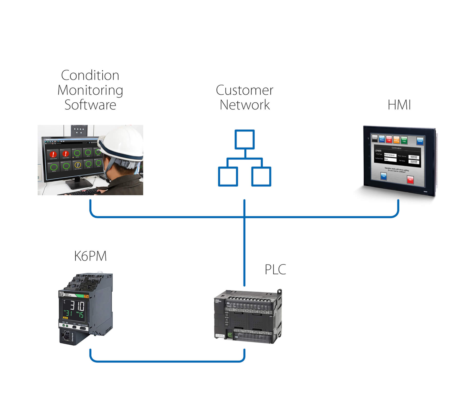
Instalacja autonomiczna (ze sterownikiem PLC)
Rozwiązanie zapewnia dodatkowe funkcje względem poprzedniej wersji:
- Monitorowanie stanu silnika poprzez oprogramowanie do monitorowania stanu, działające na komputerze PC, który jest podłączony za pomocą sterownika PLC
- Używanie zdalnego połączenia PLC do uzyskania dostępu do urządzenia K6PM w celu zdalnego monitorowania i konfiguracji
- Wywoływanie za pomocą sterownika PLC działania po każdym ostrzeżeniu/alarmie wykrytym przez K6PM
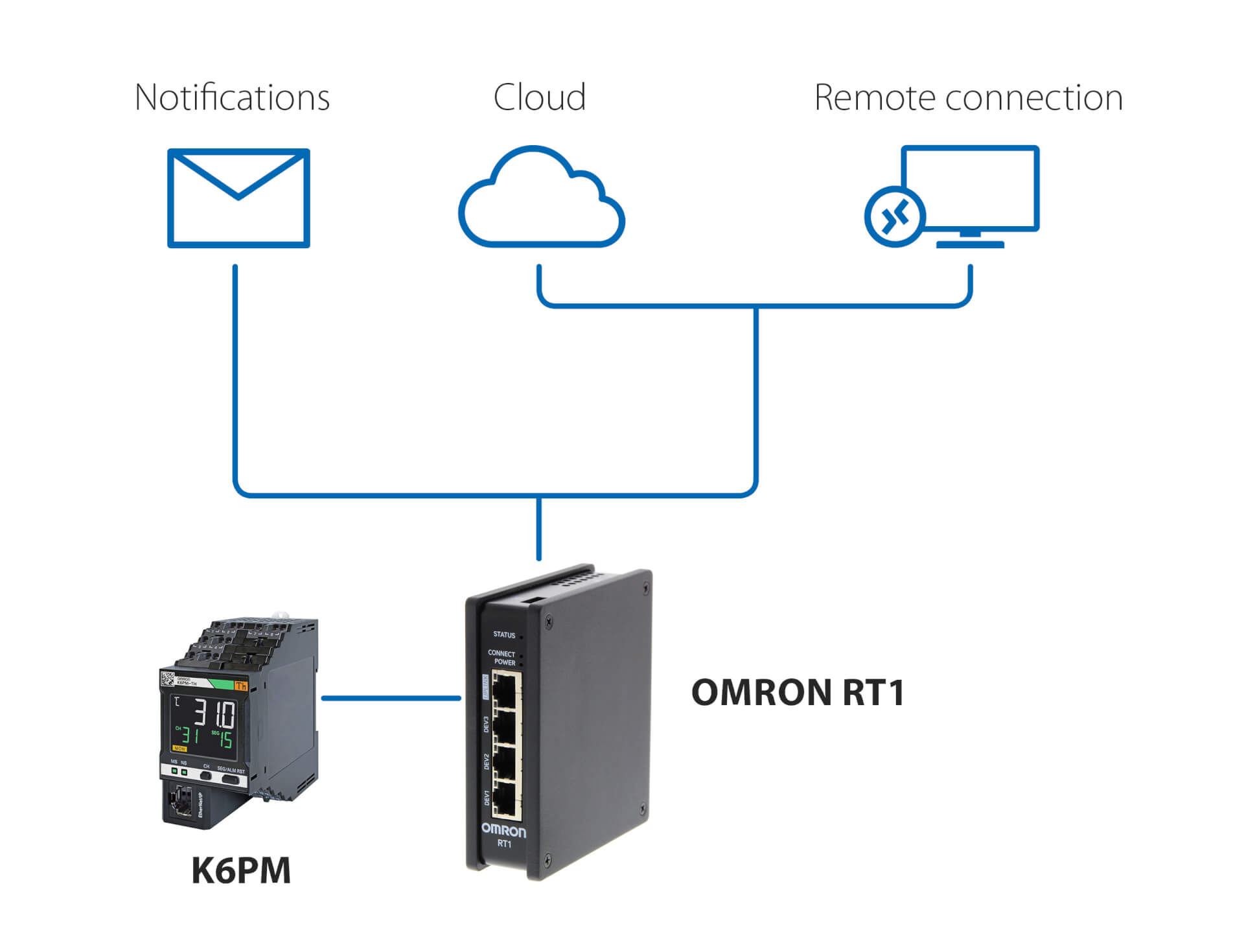
Powiadomienia i zdalne monitorowanie – bez sterownika PLC
To rozwiązanie, wykorzystujące Omron RT1 jako bramę, umożliwia:
- Korzystanie z powiadomień e-mail/SMS w przypadku wykrycia nieprawidłowości przez K6PM
- Bezpieczne połączenie (zarządzane przez RT1) z chmurą, za pośrednictwem sieci LAN lub połączenia 4G
- Bezpieczne połączenie do zdalnego monitorowania i konfiguracji K6PM za pomocą oprogramowania do monitorowania stanu dostarczonego ze sterownikiem
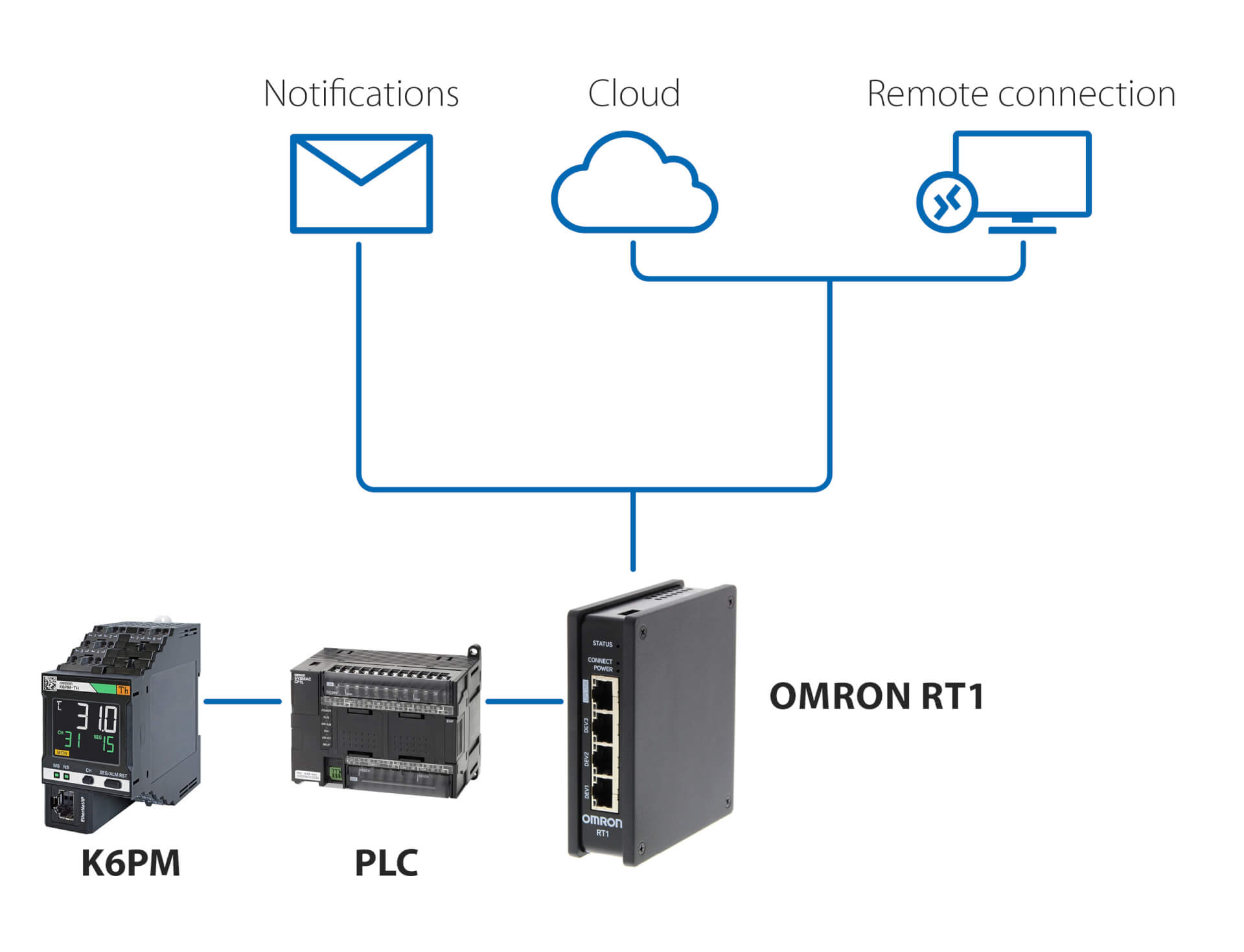
Powiadomienia i zdalne monitorowanie – ze sterownikiem PLC
To rozwiązanie, wykorzystujące dowolny sterownik PLC i Omron RT1 jako bramę, umożliwia:
- Korzystanie z powiadomień e-mail/SMS w przypadku wykrycia nieprawidłowości przez K6PM
- Bezpieczne połączenie (zarządzane przez RT1) z chmurą, za pośrednictwem sieci LAN lub połączenia 4G
- Bezpieczne połączenie do zdalnego monitorowania i konfiguracji K6PM za pomocą oprogramowania do monitorowania stanu dostarczonego ze sterownikiem
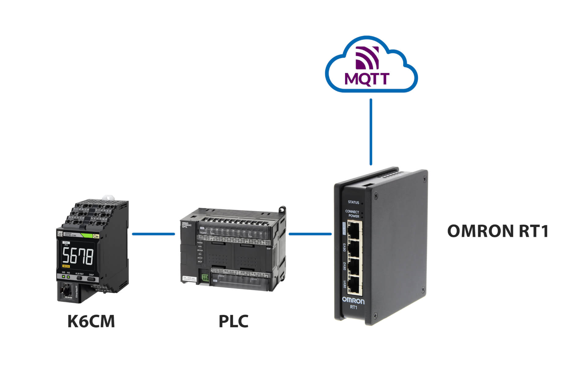
Połączenie z serwerem MQTT
Powiązane produkty
-
Urządzenie monitorujące stan silnika – monitorowanie prądu
-
Urządzenie monitorujące stan silnika – monitorowanie izolacji
-
Urządzenie monitorujące stan silnika – monitorowanie drgań
-
Urządzenie do monitorowania stanu – monitorowanie izolacji
Materiały